
In the last couple weeks I tweaked the Software a lot and the receiver now has an enclousure. Also the MS5611 (high precision Barometer chip) arrived and the Software work can finally start to get also this feature reliable.
The enclousure is made from thick plastic film. First printed and then plotted to the right dimensions. The holes for the bind Button and the Leds have also been plotted out. The edges where cut half way through, to make bending straight edges easyier. The case is then folded into shape and secured with some superglue.
 |
| DIV8RTV with enclosure |
Software wise has a lot changed from the last update. The receiver has now SmartHub enabled and also has programmable failsave. I still have to work a lot on the vario feature as the time for the heavy calculations is really limited. So far I've made 5 boards and have flown all of them without any issues up to 400m (RSSI still up to 75), limited by the size of the test plane. For almost all tests I used a HyperBipe from Hobbyking which has a wingspan of about 900mm. Nitro planes have been tested too, so vibrations are also tolerable. The total fight time of the receivers should have reached about 10 hours. As I said no issues so far.
I'll now order more parts to be able to produce in a small (for me possible to hand assemble) batch of about 50 receivers. Soldering many of these boards also requires some technics to follow while
assembling. Otherwise it'll take a lot longer and will be more harmfull
to yourself. Because of that I'll describe some details about my
assembling process in the future. Facing the use of stencils and general
soldering tips that might be useful for someone with not so much
experience.
 |
| Fresh soldered and flashed receivers |
The hardware has prooven to be working with the current layout. The only thing that will change from the first prototype is a small track to control the amplifier gain.
I noticed some swamping issues when the receiver is very close to the transmitter (about 2m radius) which is really annoing, because the transmitter is spitting out telemetry lost warnings all the time. With the then implemented software controlable gain this issue should be fixed in the next revision by disabling the power Amplifier when the RSSI is reading over 100.
I attached a few impressions of the receiver in action (of cause only in small airframes for now)
The Measurements have been made! Last week I met with one of the Assistants of the local Institute for integrated Circuit design at my University. He kindly gave me the opportunity to use one of their Lab-Places to do my measurements. Huge thanks again for that!
The equipment that I used for the tests was a Rohde & Schwarz FSV. Also a HP benchtop Power supply and a IR-Camera FLIR T430sc. So, quite nice stuff to play with!

I started by getting used to the Spectrum Analyzer... This took longer than I thought initially but I've never used an instrument like this before. After I was somewhat knowing what I was doing. I connected a antenna to the input Port and switched my FrSky Taranis on. The result was about 100mW as expected by the specification, of cause depending on the distance between the FSV and the Transmitter.
Here some snapshots of the Transmitter idleing and in Range-Test mode. I had to change the attenuation in order to get the best resolution (and not to overload the FSV).
 |
| Transmitter power X9D | 30dB Att. |
 |
| Transmitter power X9D RANGE MODE | 10dB Att. |
The first receiver now got it's output power mesuared in peak hold mode (because that was the only mode I was aware of to use on FHSS (Frequency Hopping) systems. Should have informed myself a lot more than I did, but hell yeah... To get a uni-directional measurement I added a directional coupler and of cause connected the receiver to a propper uFL to SMA adaptor.
The receiver performed as good or better than what I could have ever imagined. Almost exactly 100mW! The insertion loss of the Balun network in the RF-Section that I used may be the reson for the slight attenuation, or even mesuarement errors that I have made by compensating the directional coupler...

After that I connected one of the boards with the fake chips to the FSV. And got really suprised... The output Power is at best 1000th of the non fake chip! Also there really is not a consistent Signal comming out of these...
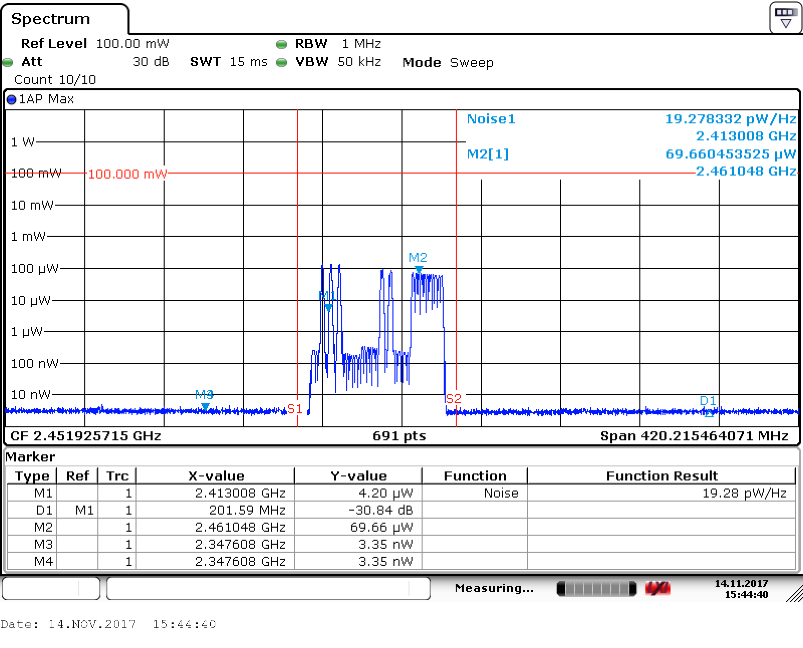 |
| Chinese ICs perform really bad! |
After doing many similar measurements on all of the other receivers, with the same results, I started playing around with the FSV. Here a shot of how channel hopping looks like (The Amplitude is not relevant, because I used averaging to make it a more smooth movement):
Also I took a few shots with a IR-Camera (FLIR T430sc). The max Temperature is not really accurate in the way we used it! These shots where just for fun...


That's it for now! I hope you enjoyed this update.
Keine Kommentare:
Kommentar veröffentlichen