Montag, 23. Mai 2016

DIY Long Range Receiver

While searching for parts to build the MC3D project I found a CC2500 module with an on board PA and LNA. The specs are really impressive. Up to 1800m range and 22dbm transmit power. So I orderd the part four weeks ago and today it arrived in the mail. Hopefully I'll be able to complete the MC3D project soon and start working on this one!

Followup for this one: http://stefansbb.blogspot.de/2017/07/div8rtv-compact-cheap-but-powerful.html?m=1


Donnerstag, 19. Mai 2016

Expanding a D4R - II to 8 channels

Today I quickly build myself a small "magic box" that is able to output 8 pwm channels (standard servo signals) from a D4R II FrSky receivers output.

You may ask why to do something like that when there are a lot of cheap 8 channel receivers out there. Well it happened (as always) to me that I run out of receivers while preparing my model airplanes for a larger RC flight event. Unfortunately I thought too late about that this time... The only receiver I had at hand was a broken D4R II and the macgyver inside me decided to try fixing and expanding it.

First things first I started troubleshooting the receiver. I measured a dead short at the voltage input. That clearly indicated a dead LDO (Low-dropout regulator). After checking the output voltage, pinout and footprint at the datasheet, I searched for a matching one in my part stock. Unfortunately I only had one in SOT-223-3 package. So I hacked that one onto the receivers PCB and sure enough, the receiver started working again!

With that done the fun part of hacking took action. Because I had no time to buildup my own hardware, I took an old 2.4Ghz (also broken) receiver apart.


Removed carefully the receiving module.

And reverse engineered the important sections like SPI interface, channel output pins, status leds and serial data lines.

Because the D4R II is able to output ppm signals on channel 1 pin for 8 channels by shorting channel 3&4 pins. I checked the output with my scope and took rough measurements and calculations.

I just had to build a PPM to pwm converter. The Atmega8 on the old receiver is more than capable doing that, so I started writing some software to analyze the PPM signal and split it. You can checkout that messy piece of code here (written in AVR GCC).


It uses the 16bit timer1 to capture the incoming PPM data and split it into data and sync. One of the 8bit timers was then used to output the servo commands. That's it!


Here the final result I came up with. 


MC3D status update

During the last weeks I was really busy so I wasn't able to work on my projects.
Yesterday I printed all the 3D parts required to finish the build. The only thing left to do before final assembly is to edit the cleanflight software, so it matches my needs. Hopefully I will finish that today. Stay tuned!

Montag, 2. Mai 2016

Lenovo G70-70 second hdd

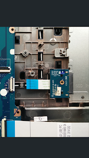
After disassembling my current laptop (a Lenovo G70-70) for cleaning, I considered to increase the storage capacity to at least the double. One possible way would be to replace the current HDD with a larger one. But I thought about using the space left inside and physically adding a second HDD. Because my model has a plastic cover instead of the optical drive a HDD caddy would be a great option. So with that in mind I removed the cover and locking screw to take a closer look inside. One important thing on adding a caddy to your laptop is to make sure there are the matching connectors fitted. Unfortunately in my case Lenovo hasn't fitted these. I took a quick look to the block diagram and found a second sata connector (SATA ODD) drawn. So I've done some research on the web and found the maintenance manual by Lenovo. On page 84 arrow 5 you can see the missing part on my version. It seems to be just a adapter board with a flat flex jumping over to the mainboard. So at least a flat flex connector should be visible on the mainboard. And after taking a really close look inside the slot I was able to see a connector. I also counted the number of pins (10) to compare to possible adapters later on. So all I need to add another HDD would be the missing odd board. After searching for hours for a suitable reseller I almost gave up. Most of the resellers (I found about 5) had really high price points for something that simple. Then I stumbled over an odd board for a Lenovo G50 on aliexpress. After checking the pincount, mounting holes and overall design I ordered the part.


Last week (20 days later) the part arrived in the mail. It was nicely packed in some bubble wrap and in good shape. So later today I disassembled my laptop in order to add the PCB. I really was confused by the amount of parts that I needed to remove just to reach the mainboard section. I removed keyboard, cooling fan and the entire keyboard bezel to get access. But the steps are pretty easy to do if you follow the maintenance manual I linked in above.
So I test fitted the odd adapter PCB and thankfully it did fit perfectly! BUT the flatflex cable was way too short... 


Thinking about possible issues why, I should have looked the G50 up. The G50 is way smaller (15,6" instead of 17.3") than my model. Thankfully the cable has standard 1mm pitch so I can easily replace that.

Yesterday I soldered a new flatflex cable out of an old cd-rom drive onto the odd board. After disassambling the laptop again I screwed the board into it's place and reassambled everything back together. Now I have to order a matching hdd caddy before I can say anything about the functionality, but the part does fit perfectly inside.


To be continued...

MC3D Project

Back in december of 2015 my brother and I decided to build another fpv multicopter. We came up with the following properties/goals to aim for:

  • tiny, we want it to be as small as possible
  • fpv equipped
  • onboard receiver for FrSky or Spektrum but still be able to use different rx as well
  • clean-/betaflight compatible
  • 1s single cell LiPo-Battery
  • 8.5mm brushed motors
  • simple mosfet driver as esc
  • 3d printed arms and landing gear
  • PCB-base plate
  • name MC3D (MultiCopter3D)


That's it for the technical aspects! As far as the design goes, we wanted something similar to the nqx980. So my brother who is into 3d-modeling started to draw a simple shape of the base plate.

Sorry for the poor image quality! At this point we haven't thought about publishing the project and only rough documented the process.

With that done I've converted the shape into a PCB outline and started drawing the schematic.

Because we're aiming for a compatible board to CC3D and others running cleanflight I choose the same stm32f1 mcu and mpu6000 accelerometer as used on a cc3d & atom. For the esc's the choice was pretty straight foreward. Small SOT32 package mosfet very simple driving circuit and some noise filtering with caps. Next was the receiver. I thought a lot about reverse engineering the protcol used by FrSky/Spektrum but never realy took it into action. So after a quick google search, to get at least some idea of the enemy, I found a post at the rcgroups forum by midelic, where he published a diy FrSky receiver. So all the fun part of reverse engineering was already done! Awesome work guys! Using something "of the shelf", I simply added his schematic into my project and linked all the necessary pins. That's it for the receiver!
So the schematic was done after just a few evenings of work and I now could focus on the layout part.

To keep the cost low, I wanted to make the board with 2 layers only instead of four. This has unfortunately some disadvantages. One of them is a increased noise floor, which really has to be considered, because we're using noise sensitive components like the mpu6000. Usually a board like this has four or more layers. Two of them with a "flood fill" to keep the inductance as low as possible. Furthermore the routing is way simpler. But as I said, we'll stay on a 2 layer pcb.
In order to get rid of at least some problems, I floodfilled both layers and attached them to ground. And to prevent slight potential differences between the layers and also for a better noisefloor I stiched the board on the surronding chip areas with vias. You might ask what has happend to the positive connection which also does provide power to all 4 main corners of the pcb for the escs? Well I really thought a lot about this one track and finally come up with just one 200-300 mil track snaking its way right at the boards edge.

At the same time my brother drew the rest of the parts. Here is what he came up with.


To get an idea of the dimensions we testprinted one arm of the frame on our diy TinyBoy.


Surprisingly the arm had a really good strength to weight ratio. Huge success!

The next weeks I spend on optimising the pcb layout and finally in mid january of 2016 I placed my order at a pcb manufacurer in china to produce our pcbs. After waiting the usual 3-4 weeks the parcel arrived in good shape in my mailbox. 

The quality was awesome! Even the large silkscreen on the bottom, covering some vias was pretty good considering the price to performance ratio.


Next step was to assemble the first prototype! Because we want to spend as little as possible we recycled almost every part of an old cc3d atom and placed them on our new board. The hardest part was to get the old leadfree solder of the pads, without damaging them. But with the iron set to a low temperature and just a minimal amount of pressure this was quickly done.
Workbench

Comparing the MPU6000 to a MicroSd
A closer look to the just soldered MPU6000


Almost finished prototype
Now the moment of truth! Lets plug it into the USB and try to flash...
And success! On first try the board connected without any problem to the Cleanflight config. After calibrating the accelerometer I had a really big smile on my face! Everything worked like a dream.
First connect ever to our first prototype
To be continued....