Mittwoch, 22. November 2017

DIV8RTV Updates and lab measurements

In the last couple weeks I tweaked the Software a lot and the receiver now has an enclousure. Also the MS5611 (high precision Barometer chip) arrived and the Software work can finally start to get also this feature reliable.
The enclousure is made from thick plastic film. First printed and then plotted to the right dimensions. The holes for the bind Button and the Leds have also been plotted out. The edges where cut half way through, to make bending straight edges easyier. The case is then folded into shape and secured with some superglue.
DIV8RTV with enclosure
Software wise has a lot changed from the last update. The receiver has now SmartHub enabled and also has programmable failsave. I still have to work a lot on the vario feature as the time for the heavy calculations is really limited. So far I've made 5 boards and have flown all of them without any issues up to 400m (RSSI still up to 75), limited by the size of the test plane. For almost all tests I used a HyperBipe from Hobbyking which has a wingspan of about 900mm. Nitro planes have been tested too, so vibrations are also tolerable. The total fight time of the receivers should have reached about 10 hours. As I said no issues so far.

I'll now order more parts to be able to produce in a small (for me possible to hand assemble) batch of about 50 receivers. Soldering many of these boards also requires some technics to follow while assembling. Otherwise it'll take a lot longer and will be more harmfull to yourself. Because of that I'll describe some details about my assembling process in the future. Facing the use of stencils and general soldering tips that might be useful for someone with not so much experience.
Fresh soldered and flashed receivers
The hardware has prooven to be working with the current layout. The only thing that will change from the first prototype is a small track to control the amplifier gain. 
I noticed some swamping issues when the receiver is very close to the transmitter (about 2m radius) which is really annoing, because the transmitter is spitting out telemetry lost warnings all the time. With the then implemented software controlable gain this issue should be fixed in the next revision by disabling the power Amplifier when the RSSI is reading over 100.

I attached a few impressions of the receiver in action (of cause only in small airframes for now)


The Measurements have been made! Last week I met with one of the Assistants of the local Institute for integrated Circuit design at my University. He kindly gave me the opportunity to use one of their Lab-Places to do my measurements. Huge thanks again for that!
The equipment that I used for the tests was a Rohde & Schwarz FSV. Also a HP benchtop Power supply and a IR-Camera FLIR T430sc. So, quite nice stuff to play with!


I started by getting used to the Spectrum Analyzer... This took longer than I thought initially but I've never used an instrument like this before. After I was somewhat knowing what I was doing. I connected a antenna to the input Port and switched my FrSky Taranis on. The result was about 100mW as expected by the specification, of cause depending on the distance between the FSV and the Transmitter.
Here some snapshots of the Transmitter idleing and in Range-Test mode. I had to change the attenuation in order to get the best resolution (and not to overload the FSV).
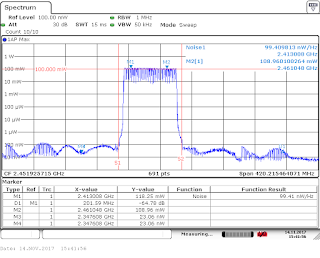
Transmitter power X9D | 30dB Att.
Transmitter power X9D RANGE MODE | 10dB Att.
I now connected the first receiver that I brought to the Lab. I brought many receivers to the Lab in order to get a more consistent result. Also I built 2 receivers with "fake" CC2500 and SE2431L from the chinese market. But more on that later...
The first receiver now got it's output power mesuared in peak hold mode (because that was the only mode I was aware of to use on FHSS (Frequency Hopping) systems. Should have informed myself a lot more than I did, but hell yeah... To get a uni-directional measurement I added a directional coupler and of cause connected the receiver to a propper uFL to SMA adaptor.
The receiver performed as good or better than what I could have ever imagined. Almost exactly 100mW! The insertion loss of the Balun network in the RF-Section that I used may be the reson for the slight attenuation, or even mesuarement errors that I have made by compensating the directional coupler...


After that I connected one of the boards with the fake chips to the FSV. And got really suprised... The output Power is at best 1000th of the non fake chip! Also there really is not a consistent Signal comming out of these...

Chinese ICs perform really bad!
I plan on taking a look inside one of these chips to see how they managed to copy the ICs. Also I may build another receiver with only the SE2431L beeing from china. To sort out only one IC not working properly. Even no I would never use these ICs in a real application, I really was quite intereseted in testing these.
After doing many similar measurements on all of the other receivers, with the same results, I started playing around with the FSV. Here a shot of how channel hopping looks like (The Amplitude is not relevant, because I used averaging to make it a more smooth movement):


Also I took a few shots with a IR-Camera (FLIR T430sc). The max Temperature is not really accurate in the way we used it! These shots where just for fun...


That's it for now! I hope you enjoyed this update.

Dienstag, 25. Juli 2017

DIV8RTV - A compact, cheap but powerful FrSky-Receiver

I finally got around to write something about the project I was working on for about 5 Month till now.
At first I'll describe something about it's features and after that I will go more into the technical aspects of the device and how I made the device itself.


Features (at the current hardware and software revision)

It's a Diversity 8 channel Receiver that features Telemetry and a high precision Variometer. With high precision Vario I mean <=10cm (delta) altitude recognition, wich is head to head with the current top of the line versions by some name Brands like Futaba. Also the Receiver has a small form factor (only 45mm x 25mm) furthermore it's relatively easy to assemble and use. Just set your Transmitter as per normal to D8 Protocol and hold the Bind button on the Receiver while switching it on. Then start the Bind sequence on the TX. After a few seconds the green Led on the Receiver will turn off. That's the binding done. The Telemetry is currently returning the current supply Voltage on the Servo Connectors, the current altitude and the current RSSI value. You can input everything from about 3.3 to 9 volts DC. The builtin protection against reverse polarity protects the Receiver from stupid mistakes, as they often happen on the field... The antennas are the same design as used by the official FrSky receivers. So if you cut one by accident you can just buy a new one, clip it on and continue flying. I also considered to enable the so called "SmartPort" feature that some official Receivers feature. That way you can connect any telemetry Item that you want. But it's not jet implemented. Additionally it features "Full-Range" capabilities by using a low noise amplifier. The practical Distance should be around 1.5 to 3km (for Telemetry a little less I think). The Receiver is now almost ready for some extensive testing in the Lab and on the field. 
Many thanks at this point to the Institute for integrated Analog and RF Circuit Design (IAS) at the RWTH-Aachen for making it possible for me to use some of their Rhode & Schwarz testing Equipment in their Laboratory. (Further Posts coming on this topic for sure!)

Design

The design was pretty straight forward, as the Protocol and Hardware used by FrSky have been discussed in many forums. Huge thanks to all of these people that have successfully reverse engineered most of the parts. Also huge thanks to fishpepper, who has made his implementation open Source. I based my Software around his one, as it is well written and easy to adjust for new hardware. 

But to get started, I've read a lot for the most part of this project in order to build up some knowledge about RF-Circuit design and the Protocol and Hardware used by FrSky. The design is a 4-Layer PCB with the inner Layers dedicated to VCC and GND. That makes routing of RF-Signals a lot easier. Especially if you don't have massive amount of knowledge and practice. But the board could be routed on a 2 Layer Board with some effort. The Design consists of a STM32F1 32Bit ARM Cortex M3 MCU and a CC2500 RF IC by Texas Instruments. Additionally I implemented a SE2431L to have a LNA (low noise amp) and PA (Power amp) on board to gain the Range. The other Components are more or less for convenience. A onboard EEprom is used to keep the current Bind and frequency offset correction information. An MS5611 is used to get the current altitude (quite expensive by the way). It get's reset to relative 0 when switched on. And some bypassing caps and filters are added as necessary. As already mentioned I used the same IPEX connectors for the antennas as FrSky does. The project is not 100% done yet, so I'll post some updates in the future and maybe make the Hard and Software OpenSource.
If you have any questions about this project don't hesitate to ask!


Donnerstag, 27. April 2017

Reverse engineering a TD025 compressor wheel shape

This is a post that I've written quite a while ago. I never released it, because I thought, that it's to boring. So keep that in mind while reading...


Some month ago I bought a compressor wheel for a TD025 turbocharger, which is a very common part used in cheaper cars, for some upcomming experiments with gas turbines. I plan to calculate and build up a gas turbine from parts that are easy to access. As the very popular DIY turbine KJ66 uses parts from an older turbocharger (which are really expensive these days), I initially came to the idea of trying to optimise the BOM (Bill of material) by using more standard parts. I plan to base my project around the existing KJ66 and MW54 as these are heavily optimised since the 1990s. Of cause changing a critical part of the design does lead to a lot of issues. The profile of the compressor wheel I plan to use is not that easy to find on the web and even after days of reasearch I wasn't pleased with the results. But because the shape is extreamly critical I thought about ways to specify the shape with simple methods.
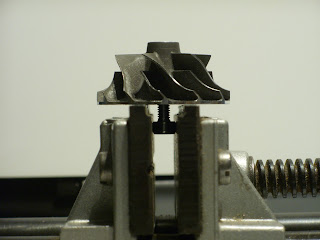
The first method that I tried was mounting the wheel to a shaft and chucking it in my drill press to carefully mill some foam to the perfect shape. This worked out okay but not as well as I was hoping it would. Even the fine styrofoam that I used was still not fine enough to highlite the profile well enough for relaiable specification. In addition the small runout of the drillpress over shaped the profile. So further tinkering was required. The next option that came to my mind was a optical method by positioning a camera perpendicular to the compressors shaft and also in the center of view to minimize any optical distortion. That way I only have to take several images from different rotation positions of the compressor and overlay them to get the shape. So I build up a very minimalistic fotobox with a white background for better contrast and even lighting. Next I took the compressor wheel and a 4mm bolt as a axis. I then used a small machining vise to secure the bolt vertical and perpendicular. I'm now able to rotate the compressor wheel with minimal runout. I now took several Images of a small rotation. For this using the cameras hands free capturing function lead to minimal movement that otherwise could have occured by pressing the shutter switch. The images then where postprocessed with a threshold filter and then overlayed. The result was, after cleaning up the noise, a crisp outline of the compressors shape. Finally I sketched a negative of the wheels shape and printed it with our 3d printer to ensure the tolerances where at the right spot. And the fit was way better then I would have tought. Even a bit to tight for my taste but that could also have been caused by the printers tolerances.