This is a post that I've written quite a while ago. I never released it, because I thought, that it's to boring. So keep that in mind while reading...
Some month ago I bought a compressor wheel for a TD025 turbocharger, which is a very common part used in cheaper cars, for some upcomming experiments with gas turbines. I plan to calculate and build up a gas turbine from parts that are easy to access. As the very popular DIY turbine KJ66 uses parts from an older turbocharger (which are really expensive these days), I initially came to the idea of trying to optimise the BOM (Bill of material) by using more standard parts. I plan to base my project around the existing KJ66 and MW54 as these are heavily optimised since the 1990s. Of cause changing a critical part of the design does lead to a lot of issues. The profile of the compressor wheel I plan to use is not that easy to find on the web and even after days of reasearch I wasn't pleased with the results. But because the shape is extreamly critical I thought about ways to specify the shape with simple methods.
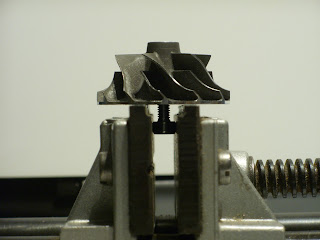
The first method that I tried was mounting the wheel to a shaft and chucking it in my drill press to carefully mill some foam to the perfect shape. This worked out okay but not as well as I was hoping it would. Even the fine styrofoam that I used was still not fine enough to highlite the profile well enough for relaiable specification. In addition the small runout of the drillpress over shaped the profile. So further tinkering was required. The next option that came to my mind was a optical method by positioning a camera perpendicular to the compressors shaft and also in the center of view to minimize any optical distortion. That way I only have to take several images from different rotation positions of the compressor and overlay them to get the shape. So I build up a very minimalistic fotobox with a white background for better contrast and even lighting. Next I took the compressor wheel and a 4mm bolt as a axis. I then used a small machining vise to secure the bolt vertical and perpendicular. I'm now able to rotate the compressor wheel with minimal runout. I now took several Images of a small rotation. For this using the cameras hands free capturing function lead to minimal movement that otherwise could have occured by pressing the shutter switch. The images then where postprocessed with a threshold filter and then overlayed. The result was, after cleaning up the noise, a crisp outline of the compressors shape. Finally I sketched a negative of the wheels shape and printed it with our 3d printer to ensure the tolerances where at the right spot. And the fit was way better then I would have tought. Even a bit to tight for my taste but that could also have been caused by the printers tolerances.
The first method that I tried was mounting the wheel to a shaft and chucking it in my drill press to carefully mill some foam to the perfect shape. This worked out okay but not as well as I was hoping it would. Even the fine styrofoam that I used was still not fine enough to highlite the profile well enough for relaiable specification. In addition the small runout of the drillpress over shaped the profile. So further tinkering was required. The next option that came to my mind was a optical method by positioning a camera perpendicular to the compressors shaft and also in the center of view to minimize any optical distortion. That way I only have to take several images from different rotation positions of the compressor and overlay them to get the shape. So I build up a very minimalistic fotobox with a white background for better contrast and even lighting. Next I took the compressor wheel and a 4mm bolt as a axis. I then used a small machining vise to secure the bolt vertical and perpendicular. I'm now able to rotate the compressor wheel with minimal runout. I now took several Images of a small rotation. For this using the cameras hands free capturing function lead to minimal movement that otherwise could have occured by pressing the shutter switch. The images then where postprocessed with a threshold filter and then overlayed. The result was, after cleaning up the noise, a crisp outline of the compressors shape. Finally I sketched a negative of the wheels shape and printed it with our 3d printer to ensure the tolerances where at the right spot. And the fit was way better then I would have tought. Even a bit to tight for my taste but that could also have been caused by the printers tolerances.


Keine Kommentare:
Kommentar veröffentlichen