Last week, I got surprisingly early my ordered parts from LCSC. I should probably mention, that Im not affiliated with LCSC in any way. I just want to share my opinion with a shop that I didn't use before.
As you may have already seen in one of my recent posts, I'm assembling a huge amount of DIY FrSky compatible receivers. Some of the parts are quite expensive (about 2.5€ each) in reasonable quantities from my usual suppliers Mouser and Digikey. This time I wanted to try one of the more trusted chinese suppliers. I have some experience with parts from Aliexpress (especially rf ones) and most of them where not worth the cost saving. This time however I ordered as already mentioned from LCSC. No hugely critical components just resistors, capacitors, some ICs (and a reel of 5000 resistors just for kicks ~5€). In total I spend about 80€ including shipping cost to Germany. The cost savings in my case are about 65% compared to the same amount of parts from my already trusted suppliers. Maybe I just had luck, but the next day the order was already marked as shipped. I have not paid any extra fees for express shipping or anything like that so that was quite impressive. Again probably having luck, my order arrived only 2 weeks after the payment at my destination. I expected the parcel to be delivered to the local customs office because of the value. Over here in Germany it's quite common to pay the customs afterwards, so you should consider that already during the shopping. In my case, I pre-calculated the possible amount that they could have charged me. But still the cost saving was so high, that I thought, it's worth a try. I can't tell at the moment how the parts will perform and whether they are out of spec or not but I will give an update to that for sure. All I can say at this point is, that they arrived in a pretty well packed box and individually labeled.
As mentioned in a previous Post about my Receiver design, I have ordered a large amount of components to assemble a lot more units. Assembling this many boards takes a lot of time. If you don't organize your workplace and every process that it's going to need to build the device prior to the assembly it will almost certainly take a lot longer. I always sort and position most of the tools and parts used during assembly with about an arm length on my desk. There is nothing is more inconvenient and annoying than having to search for stuff while dealing with fragile electronics.
There are some more changes since the last post. First of all the receivers enclosure has changed to a 3d printed one as the old one was too fragile during the extensive testing that I have done. Also the overall volume has been reduced to shorten printing times and make it more useful in small airplanes.
The next change was more an addition. The antennas are now secured with some special electronic grade silicone. This prevents the antennas from being ripped of the connector or PCB. I got the silicone from Aliexpress for about 2Euro, so no large investment for a lot more security.
And finally I changed the pinout of the auxiliary Telemetry Port to match FrSky without having to build a special cable. This was as easy as routing the pins to the matching locations on the second revision of my PCB-Layout.
This project has already been one of the most time consuming things that I have ever done in my rare spare time and that is also why it takes so long to do updates or even get new features made. However I did a lot of software work to get the vario finally running the way it should. The most time went into a bug in the Processor itself. The barometric sensor had every now and then jumping values in the order of a couple kilometers. After many tests I decided to look at the data on the I2C lanes... Sometimes the processor decides to transfer an extra byte or even a zero byte. After quite some time someone pointed me to the errata sheet from ST, where this bug was already listed with a possible workaround. The workaround is to use I2C only with DMA except for single byte transfers... For me, who has never really used DMA before, there was a steep learning curve. But after stepping into many common pitfalls and general misunderstandings I got it working. Now the sensor was responding as expected.
Another really wanted feature was a automatic gain control of the amplifier stage. The problem without these few lines of code where missing packets and even complete signal losses on short distances (about 2-3m) due to overloads in the receivers input stage. Disabling the receivers amplifier during bind and high signal periods in combination with some window comparison did the trick. Now the antennas can almost touch each other without overloading.
A huge software project for the future will be adding D16 LBT and a custom bootloader to update the firmware via the transmitter and therefore building a custom .frk file converting script. At the time I'm writing this, the first part of the d16 development is almost done. I'm already able to bind and receive channel values. I now need to look into failsave values, telemetry and lbt functionality. Last mentioned has to my knowledge not been reverse engineered entirely so some nice stuff to investigate and learn. So far the D16 protocol implementation has been a nice journey, because midelic and jry on RCGroups.com have done most of the hard work and I only have to implement it into my existing software.
As almost every RC fan I'm fascinated by model engines. Most of them are however quite expensive to buy new or even used.
By the end of 2017 I got hold of a very cheap but broken Saito radial engine. With the experience that I have built over the years of flying gas and nitro engines I was very convinced that I would be able to get also this engine back up and running. I only did a few rough calculations if for the given price it was even possible to repair without paying more than I would have for a good running used one... Immediately after the parcel arrived I wrote a list with all the broken and missing parts. The engine has already been disassembled by the previous owner, but he did a wonderful job packaging and marking all the parts. That made my job a lot easier...
The damage was quite substantial as the previous owner had an unplanned 'landing' at the airfield. With broken Cylinder, Rocker arm brackets and ripped screws there was a lot to be done. Luckily I was able to drill some of the broken screws out and save some more parts that I would have otherwise had to buy new. Also the crankshaft and the matching bearings where in good condition. Here just a few impressions. There where a lot more parts damaged but I think they illustrate it the best...
The whole cleaning and inspection took 2 days in total and afterwards I placed an order for the missing parts. Unfortunately the shop I ordered them from had to order them from Japan (Saito is a Japan company) so the delivery could have taken over 3 Month. Again having luck the parcel arrived by the middle of February. I also could have ordered the parts at a local German hobby shop but they would have cost more than twice as much.
The day the parts arrived I started sorting and assembling of the parts. Unfortunately one of the cylinders had a large leak at the exhaust valve. I decided to try to grind it in using some abrasive cleaning solvent. However it did not work at all. Maybe if I would have ground it a lot longer than I already did. After that I bought a proper valve grinding kit for a few Euros. This grinding paste was way more on the coarse side and made fast work of the leak. Another night of valve grinding and screwing parts together later I had 2 cylinders in place with decent compression. The third cylinder got assembled in the following morning. The engine got to me with a Keleo customs exhaust. It was in really bad shape too. Having no exhaust but a ready to run engine I took a flip without a muffler. It fired up at the third try and ran pretty smooth afterwards.
With that result I was really happy having invested in the broken parts only the muffler being an open issue. Two weeks later I tried to get the muffler back into shape. Propane torch, huge clamps and a vise later I finally got it, so that it would fit the engine again. It's certainly not a thing of beauty anymore but the sound will not be affected by that. And as it will be screwed under a hood it won't be seen too.
Hopefully the repairs will last a long time and I will find a suitable airframe in the future.
In the last couple weeks I tweaked the Software a lot and the receiver now has an enclousure. Also the MS5611 (high precision Barometer chip) arrived and the Software work can finally start to get also this feature reliable.
The enclousure is made from thick plastic film. First printed and then plotted to the right dimensions. The holes for the bind Button and the Leds have also been plotted out. The edges where cut half way through, to make bending straight edges easyier. The case is then folded into shape and secured with some superglue.
DIV8RTV with enclosure
Software wise has a lot changed from the last update. The receiver has now SmartHub enabled and also has programmable failsave. I still have to work a lot on the vario feature as the time for the heavy calculations is really limited. So far I've made 5 boards and have flown all of them without any issues up to 400m (RSSI still up to 75), limited by the size of the test plane. For almost all tests I used a HyperBipe from Hobbyking which has a wingspan of about 900mm. Nitro planes have been tested too, so vibrations are also tolerable. The total fight time of the receivers should have reached about 10 hours. As I said no issues so far.
I'll now order more parts to be able to produce in a small (for me possible to hand assemble) batch of about 50 receivers. Soldering many of these boards also requires some technics to follow while
assembling. Otherwise it'll take a lot longer and will be more harmfull
to yourself. Because of that I'll describe some details about my
assembling process in the future. Facing the use of stencils and general
soldering tips that might be useful for someone with not so much
experience.
Fresh soldered and flashed receivers
The hardware has prooven to be working with the current layout. The only thing that will change from the first prototype is a small track to control the amplifier gain.
I noticed some swamping issues when the receiver is very close to the transmitter (about 2m radius) which is really annoing, because the transmitter is spitting out telemetry lost warnings all the time. With the then implemented software controlable gain this issue should be fixed in the next revision by disabling the power Amplifier when the RSSI is reading over 100.
I attached a few impressions of the receiver in action (of cause only in small airframes for now)
The Measurements have been made! Last week I met with one of the Assistants of the local Institute for integrated Circuit design at my University. He kindly gave me the opportunity to use one of their Lab-Places to do my measurements. Huge thanks again for that!
The equipment that I used for the tests was a Rohde & Schwarz FSV. Also a HP benchtop Power supply and a IR-Camera FLIR T430sc. So, quite nice stuff to play with!
I started by getting used to the Spectrum Analyzer... This took longer than I thought initially but I've never used an instrument like this before. After I was somewhat knowing what I was doing. I connected a antenna to the input Port and switched my FrSky Taranis on. The result was about 100mW as expected by the specification, of cause depending on the distance between the FSV and the Transmitter.
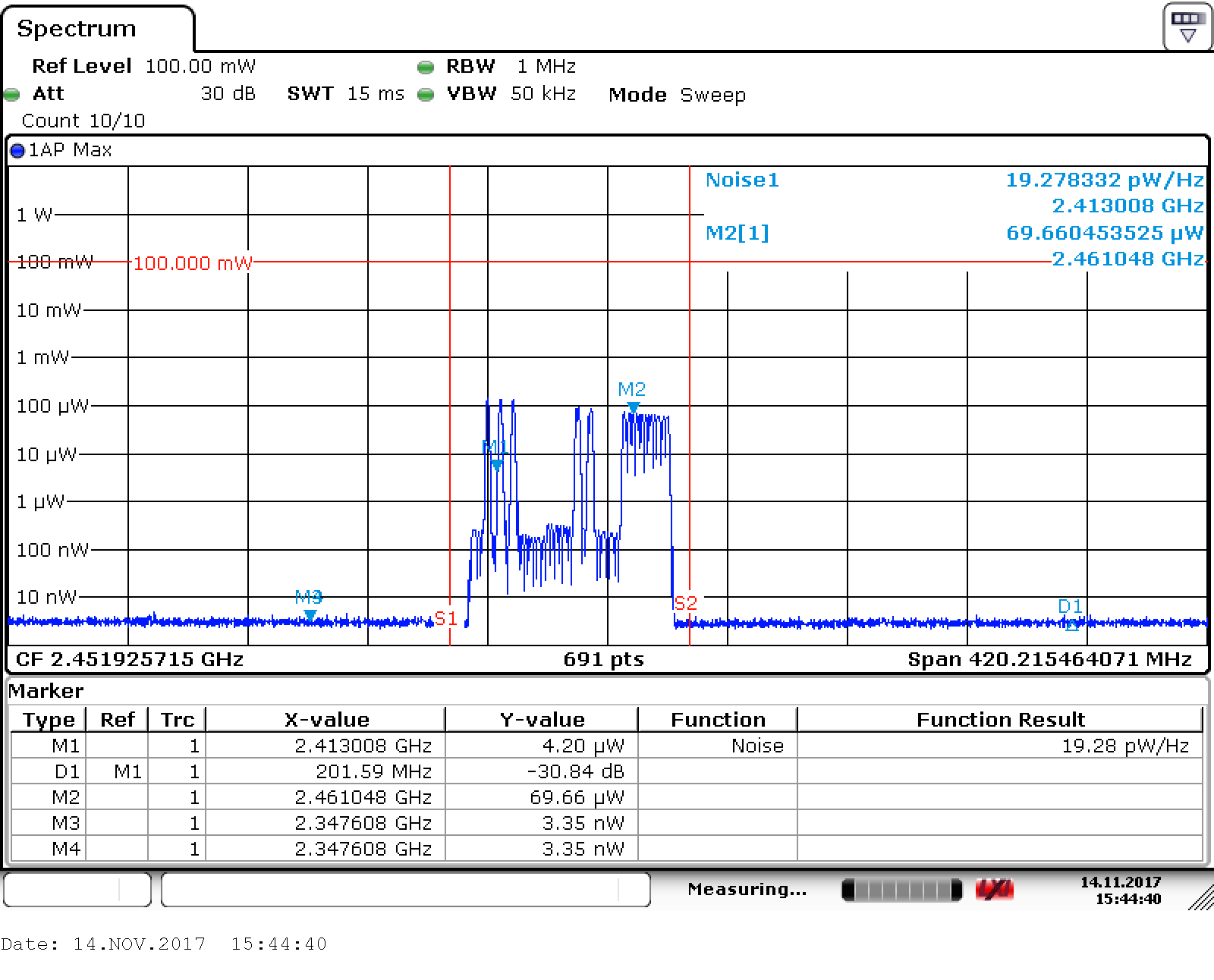
Here some snapshots of the Transmitter idleing and in Range-Test mode. I had to change the attenuation in order to get the best resolution (and not to overload the FSV).
Transmitter power X9D | 30dB Att.
Transmitter power X9D RANGE MODE | 10dB Att.
I now connected the first receiver that I brought to the Lab. I brought many receivers to the Lab in order to get a more consistent result. Also I built 2 receivers with "fake" CC2500 and SE2431L from the chinese market. But more on that later...
The first receiver now got it's output power mesuared in peak hold mode (because that was the only mode I was aware of to use on FHSS (Frequency Hopping) systems. Should have informed myself a lot more than I did, but hell yeah... To get a uni-directional measurement I added a directional coupler and of cause connected the receiver to a propper uFL to SMA adaptor.
The receiver performed as good or better than what I could have ever imagined. Almost exactly 100mW! The insertion loss of the Balun network in the RF-Section that I used may be the reson for the slight attenuation, or even mesuarement errors that I have made by compensating the directional coupler...
After that I connected one of the boards with the fake chips to the FSV. And got really suprised... The output Power is at best 1000th of the non fake chip! Also there really is not a consistent Signal comming out of these...
Chinese ICs perform really bad!
I plan on taking a look inside one of these chips to see how they managed to copy the ICs. Also I may build another receiver with only the SE2431L beeing from china. To sort out only one IC not working properly. Even no I would never use these ICs in a real application, I really was quite intereseted in testing these.
After doing many similar measurements on all of the other receivers, with the same results, I started playing around with the FSV. Here a shot of how channel hopping looks like (The Amplitude is not relevant, because I used averaging to make it a more smooth movement):
Also I took a few shots with a IR-Camera (FLIR T430sc). The max Temperature is not really accurate in the way we used it! These shots where just for fun...
That's it for now! I hope you enjoyed this update.
I finally got around to write something about the project I was working on for about 5 Month till now.
At first I'll describe something about it's features and after that I will go more into the technical aspects of the device and how I made the device itself.
Features (at the current hardware and software revision)
It's a Diversity 8 channel Receiver that features Telemetry and a high precision Variometer. With high precision Vario I mean <=10cm (delta) altitude recognition, wich is head to head with the current top of the line versions by some name Brands like Futaba. Also the Receiver has a small form factor (only 45mm x 25mm) furthermore it's relatively easy to assemble and use. Just set your Transmitter as per normal to D8 Protocol and hold the Bind button on the Receiver while switching it on. Then start the Bind sequence on the TX. After a few seconds the green Led on the Receiver will turn off. That's the binding done. The Telemetry is currently returning the current supply Voltage on the Servo Connectors, the current altitude and the current RSSI value. You can input everything from about 3.3 to 9 volts DC. The builtin protection against reverse polarity protects the Receiver from stupid mistakes, as they often happen on the field... The antennas are the same design as used by the official FrSky receivers. So if you cut one by accident you can just buy a new one, clip it on and continue flying. I also considered to enable the so called "SmartPort" feature that some official Receivers feature. That way you can connect any telemetry Item that you want. But it's not jet implemented. Additionally it features "Full-Range" capabilities by using a low noise amplifier. The practical Distance should be around 1.5 to 3km (for Telemetry a little less I think). The Receiver is now almost ready for some extensive testing in the Lab and on the field.
Many thanks at this point to the Institute for integrated Analog and RF Circuit Design (IAS) at the RWTH-Aachen for making it possible for me to use some of their Rhode & Schwarz testing Equipment in their Laboratory. (Further Posts coming on this topic for sure!)
Design
The design was pretty straight forward, as the Protocol and Hardware used by FrSky have been discussed in many forums. Huge thanks to all of these people that have successfully reverse engineered most of the parts. Also huge thanks to fishpepper, who has made his implementation open Source. I based my Software around his one, as it is well written and easy to adjust for new hardware.
But to get started, I've read a lot for the most part of this project in order to build up some knowledge about RF-Circuit design and the Protocol and Hardware used by FrSky. The design is a 4-Layer PCB with the inner Layers dedicated to VCC and GND. That makes routing of RF-Signals a lot easier. Especially if you don't have massive amount of knowledge and practice. But the board could be routed on a 2 Layer Board with some effort. The Design consists of a STM32F1 32Bit ARM Cortex M3 MCU and a CC2500 RF IC by Texas Instruments. Additionally I implemented a SE2431L to have a LNA (low noise amp) and PA (Power amp) on board to gain the Range. The other Components are more or less for convenience. A onboard EEprom is used to keep the current Bind and frequency offset correction information. An MS5611 is used to get the current altitude (quite expensive by the way). It get's reset to relative 0 when switched on. And some bypassing caps and filters are added as necessary. As already mentioned I used the same IPEX connectors for the antennas as FrSky does. The project is not 100% done yet, so I'll post some updates in the future and maybe make the Hard and Software OpenSource.
If you have any questions about this project don't hesitate to ask!
This is a post that I've written quite a while ago. I never released it, because I thought, that it's to boring. So keep that in mind while reading...
Some month ago I bought a compressor wheel for a TD025 turbocharger, which is a very common part used in cheaper cars, for some upcomming experiments with gas turbines. I plan to calculate and build up a gas turbine from parts that are easy to access. As the very popular DIY turbine KJ66 uses parts from an older turbocharger (which are really expensive these days), I initially came to the idea of trying to optimise the BOM (Bill of material) by using more standard parts. I plan to base my project around the existing KJ66 and MW54 as these are heavily optimised since the 1990s. Of cause changing a critical part of the design does lead to a lot of issues. The profile of the compressor wheel I plan to use is not that easy to find on the web and even after days of reasearch I wasn't pleased with the results. But because the shape is extreamly critical I thought about ways to specify the shape with simple methods.
The first method that I tried was mounting the wheel to a shaft and chucking it in my drill press to carefully mill some foam to the perfect shape. This worked out okay but not as well as I was hoping it would. Even the fine styrofoam that I used was still not fine enough to highlite the profile well enough for relaiable specification. In addition the small runout of the drillpress over shaped the profile. So further tinkering was required. The next option that came to my mind was a optical method by positioning a camera perpendicular to the compressors shaft and also in the center of view to minimize any optical distortion. That way I only have to take several images from different rotation positions of the compressor and overlay them to get the shape. So I build up a very minimalistic fotobox with a white background for better contrast and even lighting. Next I took the compressor wheel and a 4mm bolt as a axis. I then used a small machining vise to secure the bolt vertical and perpendicular. I'm now able to rotate the compressor wheel with minimal runout. I now took several Images of a small rotation. For this using the cameras hands free capturing function lead to minimal movement that otherwise could have occured by pressing the shutter switch. The images then where postprocessed with a threshold filter and then overlayed. The result was, after cleaning up the noise, a crisp outline of the compressors shape. Finally I sketched a negative of the wheels shape and printed it with our 3d printer to ensure the tolerances where at the right spot. And the fit was way better then I would have tought. Even a bit to tight for my taste but that could also have been caused by the printers tolerances.
As described in an earlier Post, I hacked the Ricoh toner cartridge page counter in order to be able to refill them. Today I finally got around to draw a small box-shaped enclosure with four small pogo pins as the connecting element between the MCU and the cartridge. Because the flashing process does require external power, I added a standard USB-cable to connect to any 5V supply available. This really is handy, because the printer's USB port does also work just fine. As far as the circuit goes nothing really has changed. I added a 3mm yellow led to light up while flashing of the cartridge is in progress. In addition it does flash continuously on and off, if writing or reading back has failed. The Software is slowed down a lot to ensure good physical connection and a stable state inside of the cartridge's IC. Using the device works as follows:
- Attach the device to a power supply
- Align the device with the cartridge
- Wait for the yellow led to light up
- Wait until the led goes off
- done! If the led does flash instead of continuously off, start from step one again.
The finished "product"
The advantage of using pogo pins -> perfect contact for each pin!
Say hello to my new precision laboratory power supply! I lusted after a good precision and adjustable power supply for years. Finally a week ago I decided to look after one that does fit my requirements. I was searching for at least two adjustable outputs, constant current and voltage mode, a sequencing funktion and a nice user interface. Of cause you'll find a lot of power supplys with these specs as they are really common, but on the user interface side most of them suck. The probably worst UI I've ever used was a Siglent unit and according to a few YouTube videos nothing has changed in the newer models, they still suck. For power supplys with that price to performance ratio a shame... Next brand on my list was GWInstek. Unfortunately these units are waaay out of my budget, so I continued with Korad units. Because I used these power supplys before I already knew their value.
Most of the smaller units only have one output and only 'for the price adequate' precision. But I still left them in mind in case I don't find something more suitable. Then I considered buing a used Rigol as they are a dream to use an really well build. You may have seen my hacked Rigol Oscilloscope on some of my other Blogs and I'm really in love with the usabillity and specs. Buying a new unit wasn't worth thinking about... About 900€ are really high for a hobby use powersupply. But after searching on eBay I found a auction for a DP831A. I placed it on my viewing list and stopped searching for that night. The next day the auction was going to end. I placed my bid and suprisingly got the unit for a reasonable price.
Just a few days later the unit arrived in good shape. I hope the supply will be worth the money I spend for my usecases.
After two nights of messy code work I finally got my Testboard transmitting BIND packets. In other words I'm able to bind to a receiver and establish a connection. I did a few stupid mistakes, for example I swapped milliseconds and microseconds... But even here, in my non regular Workspace, without my Oscilloscope etc. I got it to work in almost no time at all. So far everything seems to be a little bit too easy. Even my code compiled on first attempt... SCARY!
I hope that I'll get it to transmit data packets until this weekend, so that I can try the functionality and stability of the connection on the airfield.
Short post this time, but I just wanted to keep you up to date.
In addition I attached a small Video to show you what I achieved so far. After I pressed the button on the Testboard you can see the receiver flashing and the transmitter lighing up as well.
Sorry for the poor video quality but it was already past midnight as I shot it.
A friend of mine pointed me into a totally different topic a couple days ago. He said he has heard about a firmware for the popular FrSky-Taranis, which I own too by the way, with which you can use Futaba and some other protocol receivers in addition to the standard FrSky ones.
Because this really sounds interesting and also really plausible, I did a quick Google search on that topic. Unfortunately I found nothing but a YouTube-Video which is clearly a Fake. The person in the Video has done just a small change to the OpenTx-Firmware and ran it on the Simulator. So nothing special there, just a different GUI. I also found some plug-in Modules which contain multiple HF-Modules to be able to talk to other protocol receivers. But this was not what I was aiming for.
I want to be able to use the stock Hardware and a modded firmware to talk to other protocol receivers.
After that I took apart my own Transmitter in order to see whether thats a plausible thing to do or not. In fact FrSky is using just a plugin module (XJT - Module, well known) as their main transmitter unit. But thats nothing special, they're clearly cutting the cost down by doing so. All the approvals and the design afford costs an awful amount of money and this way they can do changes or even a whole new transmitter without getting everything done again. As expected they used a small STM32 controller on the XJT module just to deal with all the protocol and telemetry stuff.
In addition to that they're holding that way their protocol secret and untouched by the OpenTx firmware. This last point is unfortunately the end for any further thoughts about just changing main processor firmware to be able to use other protocols because you'll need direct access to the RF IC. (This clearly proves my opinion to the video that I mentioned earlier)
But as always I just can't stop thinking about possible ways to hack something! So I took a closer look to the board and investigated some parts of it. And yes there are at least two ways to maybe get it done. Because the builtin XJT module uses just a standard CC2500 (like my MC3D as well) and a power Amp to boost it up, all protocols that are transmittable with that hardware are theoretically possible to use. So the first option that came into my mind is to cut either in soft or in hardware the connection between the existing CC2500 and the Coprocessor. This way I could inject my own protocol and transmit it via the existing hardware. The other idea I had was to replace the existing XJT by a self-made one. That way I could flash protocols to the module until the Flash of the processor is full. Of cause reverse engineering the entire XJT module would also be a possible option to go for but as far as I can see they have used a 4 layer PCB which makes reverse engineering a lot less comfortable. As you may have seen in a earlier Blog I own a CC2500 module with an onboard LNA and PA so in fact just the same hardware as in the transmitter used.
I thought to myself that if I'm able to talk via that module to at least Futaba and FrSky receivers, I'll go for one of the above mentioned options and hack the transmitter.
On the same day I started to build-up a prototype board with just a small cortex M3 and the Transceiver module. So all the messy software stuff can now be done without going out of order with my "daily" Transmitter. I hope you liked that this time really theoretical article and stay tuned for more!
I finally had some spare time to complete the MC3D project. After a lot of issues I had with the Firmware like Failsave and Pinconfig everything seems to work just fine now. All missing 3D printed parts and motors got attached.
First start!
I carefully armed the board and pushed the throttle stick gently upwards. I'm flying mode 1 by the way. The rotors started spinning and with just a little more throttle he took off the ground. The stabilisation system did his job really well and apart from the really way too high control rates I had nothing to complain. PID wise I'm using Luxfloat and standard betaflight parameters.
After this first successfull flight I attached the cheap Banggood FPV camera to the frame with some Hotsnod and connected all the neccessary wireing. I used this camera before and it's one of the best FPV cameras I've seen so far. And also with just about 9$ you get a wide angle camera that actually performs like a really large and also often expensive one.
I then set up my FPV-Goggles. After checking everything I took off again. This time with the Goggles in front of my eyes. And as I expected I got lines crossing my field of view as soon as I the Motor PWM kicks in. They are actualy so strong visible that I can't event take off. So a filter for the camera and Video transmitter is neccessary to solve this.
To become some idea about the actual size of the problem, I attached my Scope and took a closer look to the unregulated Powerrail.
As clearly visible the 32kHz PWM takes the biggest part of the entire noise.
Of cause I did a first job by adding some capacitance across each motor while designing the circuit, but as clearly visible some noise found it's way out.
Because I don't know how the more sensitive parts on the PCB react to that, I plan to filter right at the motors to reduce the overall noise level. Hopefully the FPV issue can be solved as well by doing so. That's it unfortunately for today about the MC3D. All I can say so far is that I'm really proud of this little guy. I hope you liked the small update on that project. More stuff coming up soon!
I recently received the STM32F469 Discovery Board! It features a MiPi DSI Display with capacitive touch an SRAM for buffering Frames, a micro sd card slot, audio and so on... Because it's the same processor that I want to use in my new design and because there is really good support with exampels, I plan to complete almost all Software work on this platform before starting to buildup my own hardware. Just to make sure I dont't miss something important.
I've already successfully deployed TochGFX by Draupner Graphics, which blew my socks off! They seem to take their motto 'outstanding graphics and smooth animations with minimal resource and power consumption' really seriosly! You should check it out if you plan a project with a GUI.
Finally I can say for sure, that you can expand your storage capacity by adding an odd board to your G70-70! I searched quite a while for a good price to performance SSD and finally bought a really fast (500+mb/s) one made by Transcend. It was due to Amazons prime day also really cheap.
All that's left to say is that there is unfortunately a small issue with the covering of the odd slot. The original odd dummy has a unconventional round edge which is near to impossible to find on the web and I'm still searching for the best solution.
Untortunatly due to the exam phase at my University I really have no time to work on my projects. But this weekend I decided to try to repair a broken TV box. The box is an Allwinner H3 based single chip device (Beelink XII), running Android 4.4.2..
One day the box wasn't powering up at all and because it was in a working condition on last shutdown I thought about a software issue. I started with trying to flash the latest stock firmware but no success. In addition I got no response by the Software on connect of the device. So the device was unreachable bricked.
After some reasearch I found the linux-sunxi website which offers really good reference information about almost all Allwinner SOCs. And as always If you're trying to fix or reverse engineer something, spending some time on a good research for informations is always well spend time.
With the new knowledge about these devices I now soldered some wires to the serial interface pads on the boxes mainboard. And after powering up the device I got some output about the boot process.
So far so good So at least the processor wasn't dead. Also boot0 and uBoot seemed to be in a working condition. This also means that the nand flash was at least not entirely broken. Good news for the further process.
I now tried to build a bootable SDCard for further digging into the boot issue from the nand. But after serveral hours of image building compiling and copying files I stopped the repair session for that night (It was already 4 o'clock in the morning).
Later that day I thought about searching for possible issues of the box in the serial output. And there was indeed a really strange line which I missed out before (last line in first screenshot). Dram value=1. I tought either that is just an index or it's the actual size of the RAM. If it's the actual value of the RAM there was something entirely wrong happening.
And because the box was already broken I fired up my reflow soldering station and started to preheat the Pcb. After that I reflowed the RAM modules and let everything cool down to room temperature.
Now the final test, will it work at all after that?
YES it does! Now the output of the console showed up the correct 1Gib capacity and also the blue light came back on and the device was booting properly.
So just that tiny little line in the serial output pointed me into the right direction and saved another device from being tossed out into the garbage. I hope I can motivate you to repair some gear yourself and trust me the feeling when you got it back up is just outstanding. In addition you always lern a lot about the devices and how they work.
PS: After several checks I can say that also the overall speed has also increased by at least 15%. Therefore a production fault can be a possible reason why the box stopped working.
In the last 3 Years I have built a few different smartwatches for myself.
Im not a typical smartwatch user but really interestet into the technology involved to build them.
Most of the watches that I've build had a small 8-bit Atmel, a HC06 for the Bluetooth communication and a oled dotmatrix display. As smartwatches became more popular google released a watch version of their android called android wear and I thought about building a new watch. But this time a really powerfull one with a ARM processor running android wear or a custom os.
And because this wasn't crazy enough I decided to use a round display with capacitive touch. After some research I found a round 1.5" lcd with free viewing angle. The interface on this lcd is called MIPI-DSI. This interface type is used in almost all newer smartphones and wearable devices, because it uses only a differential serial signal to transmit the LVDS signals to the display. Also this display features a serial capacitive touch interface. I ordered the display and a few days later it arrived in my mailbox. Now it was time to search for a matching processor. I found some ready-made platforms by a Chinese manufacturer and considered using them. At the time I found their website (about 1 1/2 Years ago) they haven't offered a complete solution as there doing at the moment I'm writing this blog. But the M200 SOC had almost everything I need. A Mipi interface, serial touch, small form factor, low power consumption and it is capable running android.
Unfortunately the project suspended until now, because I was too busy and a project like that really needs a lot of time... The only thing that is stopping me at the moment from buying one of their development platforms is the bad documentation. I really don't want to spend a lot of money for a board that I'm not capable using. Another point is that I would need to build a adapter pcb for at least the display and touch interface. Also software wise I don't really know if I'm capable enough writing my own lcd driver for this SOC... Because of these arguments I searched further for some alternatives . Fortunately ST Microelectronics released a few new Cortex M4 processors (STM32F469 for example) including a MIPI interface. They also feature a graphics accelerator Chrom ART to enable smartphone like graphics. I love the way ST does their documentation so using their processor should be doable. Unfortunately using this processor would cause me to write my own watch os, because android would not run on this processor (as far as I know). At the moment I don't know which way to go. Let me know your opinion to this in the comment section!
While searching for parts to build the MC3D project I found a CC2500 module with an on board PA and LNA. The specs are really impressive. Up to 1800m range and 22dbm transmit power. So I orderd the part four weeks ago and today it arrived in the mail. Hopefully I'll be able to complete the MC3D project soon and start working on this one!
Followup for this one: http://stefansbb.blogspot.de/2017/07/div8rtv-compact-cheap-but-powerful.html?m=1
Today I quickly build myself a small "magic box" that is able to output 8 pwm channels (standard servo signals) from a D4R II FrSky receivers output.
You may ask why to do something like that when there are a lot of cheap 8 channel receivers out there. Well it happened (as always) to me that I run out of receivers while preparing my model airplanes for a larger RC flight event. Unfortunately I thought too late about that this time... The only receiver I had at hand was a broken D4R II and the macgyver inside me decided to try fixing and expanding it.
First things first I started troubleshooting the receiver. I measured a dead short at the voltage input. That clearly indicated a dead LDO (Low-dropout regulator). After checking the output voltage, pinout and footprint at the datasheet, I searched for a matching one in my part stock. Unfortunately I only had one in SOT-223-3 package. So I hacked that one onto the receivers PCB and sure enough, the receiver started working again!
With that done the fun part of hacking took action. Because I had no time to buildup my own hardware, I took an old 2.4Ghz (also broken) receiver apart.
Removed carefully the receiving module.
And reverse engineered the important sections like SPI interface, channel output pins, status leds and serial data lines.
Because the D4R II is able to output ppm signals on channel 1 pin for 8 channels by shorting channel 3&4 pins. I checked the output with my scope and took rough measurements and calculations.
I just had to build a PPM to pwm converter. The Atmega8 on the old receiver is more than capable doing that, so I started writing some software to analyze the PPM signal and split it. You can checkout that messy piece of code here (written in AVR GCC).
It uses the 16bit timer1 to capture the incoming PPM data and split it into data and sync. One of the 8bit timers was then used to output the servo commands. That's it!
During the last weeks I was really busy so I wasn't able to work on my projects.
Yesterday I printed all the 3D parts required to finish the build. The only thing left to do before final assembly is to edit the cleanflight software, so it matches my needs. Hopefully I will finish that today. Stay tuned!
After disassembling my current laptop (a Lenovo G70-70) for cleaning, I considered to increase the storage capacity to at least the double. One possible way would be to replace the current HDD with a larger one. But I thought about using the space left inside and physically adding a second HDD. Because my model has a plastic cover instead of the optical drive a HDD caddy would be a great option. So with that in mind I removed the cover and locking screw to take a closer look inside. One important thing on adding a caddy to your laptop is to make sure there are the matching connectors fitted. Unfortunately in my case Lenovo hasn't fitted these. I took a quick look to the block diagram and found a second sata connector (SATA ODD) drawn. So I've done some research on the web and found the maintenance manual by Lenovo. On page 84 arrow 5 you can see the missing part on my version. It seems to be just a adapter board with a flat flex jumping over to the mainboard. So at least a flat flex connector should be visible on the mainboard. And after taking a really close look inside the slot I was able to see a connector. I also counted the number of pins (10) to compare to possible adapters later on. So all I need to add another HDD would be the missing odd board. After searching for hours for a suitable reseller I almost gave up. Most of the resellers (I found about 5) had really high price points for something that simple. Then I stumbled over an odd board for a Lenovo G50 on aliexpress. After checking the pincount, mounting holes and overall design I ordered the part.
Last week (20 days later) the part arrived in the mail. It was nicely packed in some bubble wrap and in good shape. So later today I disassembled my laptop in order to add the PCB. I really was confused by the amount of parts that I needed to remove just to reach the mainboard section. I removed keyboard, cooling fan and the entire keyboard bezel to get access. But the steps are pretty easy to do if you follow the maintenance manual I linked in above.
So I test fitted the odd adapter PCB and thankfully it did fit perfectly! BUT the flatflex cable was way too short...
Thinking about possible issues why, I should have looked the G50 up. The G50 is way smaller (15,6" instead of 17.3") than my model. Thankfully the cable has standard 1mm pitch so I can easily replace that.
Yesterday I soldered a new flatflex cable out of an old cd-rom drive onto the odd board. After disassambling the laptop again I screwed the board into it's place and reassambled everything back together. Now I have to order a matching hdd caddy before I can say anything about the functionality, but the part does fit perfectly inside.